

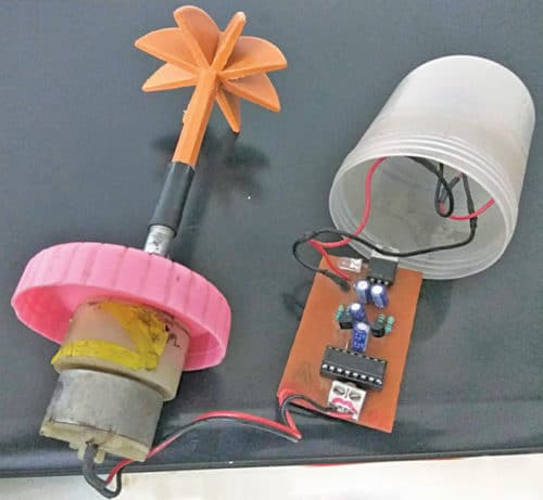
Mixing liquids using a muddler or churner is a traditional technique. However, it is time-consuming and sometimes fails to mix these properly. Here is a low-cost and versatile hand mixer circuit. It can be used for making stuff like lassi, chhach (buttermilk), butter and lemonade, among others. The author’s prototype is shown in Fig. 1.
Circuit and working for Low-Cost Versatile Hand Mixer
The circuit diagram of the low-cost and versatile hand mixer is shown in Fig. 2. It is built around 5V voltage regulator (IC1), two BC547 transistors (T1 and T2), motor driver L293D (IC2), 12V geared motor (M1) and a few other components.
Transistors T1 and T2 along with resistors R2 through R5 and capacitors C2 and C3 are configured as an astable multivibrator. Resistors R2 and R5 are connected as pull-up resistors. Resistors R3 and R4, and C2 and C3 are used for time period constants. You may change these values as per your requirement.
IC2 is used to drive motor M1. It is a dual H-bridge motor driver IC for driving the motor in clockwise as well as anti-clockwise directions.
IC1 (7805) is used as a power supply regulator. It gives constant 5V supply to power the astable multivibrator and IC2. Resistor R1 connected with LED1 is used to indicate power-on status. You can power up the circuit by connecting the power supply to connector CON1 using either 12V battery, 12V adaptor or 12V solar panel.
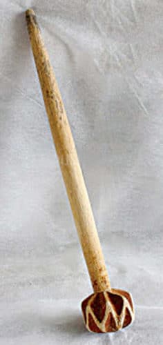
The churner is built around a DC geared motor. Its working is the same as the traditional method using hands. When you power on the circuit using switch S1, the geared motor first rotates the churner clockwise and then anti-clockwise. The cycle repeats until the contents are mixed properly. A traditional churner is shown in Fig. 3.
Construction and testing
An actual-size PCB layout for the low-cost and versatile hand mixer is shown in Fig. 4 and its components layout in Fig. 5. After assembling the circuit on the PCB, connect 12V across CON1. Connect 12V, 500- to 1000-rpm geared motor across M1.
Download PCB and component layout PDFs: click here
To use with a motor, take a muddler or churner and cut its rod as per required length. Then, take an old marker pen. Cut both ends of the same according to required length.
Stick the churner head to the motor shaft using the marker pen. To give it a finished looked, take a cylindrical container of suitable size, place the PCB inside and attach the motor to the lid cover. Fix on/off switch inside or on the enclosure for powering up the circuit. Your low-cost hand mixer is ready for use.
The author’s final product in which assembled PCB is fitted inside the plastic box is shown in Fig. 6.
Pranav R. Rokde and Shubham P. Talkhande are electronics hobbyists
This content was originally published here.


