The serious drawback of the Transformerless power supply is the low current at the output. So we can’t drive loads that require more than 75 mA current, mainly High watt LEDs and Relay driver circuits. As a rule, 75 mA current will be available per uF capacitance. But this is theoretical and in practical situation, it will be less than 75 mA, because of the low input voltage, quality of capacitor etc. But we can increase the output current to 400 mA or higher using this circuit. It can be used to light High power LEDs, Relay driver circuit etc. One condition is must. The circuit should be enclosed in a shock proof case without any contact point outside the case. Such circuits should not be used as External battery chargers since the output is at mains potential.
Just connect two or more capacitors in parallel to increase the output of this high current Transformerless power supply. As you know when we connect the non polarized capacitors in parallel, the capacitance doubles .This increases the output current. In the circuit given below, two 1 uF ( 105J 400V ) capacitors are connected in parallel. Remember, the capacitors should be in the X class and with a voltage rating 400V or 600V. See what happens when the 230V AC passes through the Parallel capacitors.
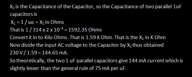
We use two 1uF capacitors. So total capacitance will be 2 uF ( 1uF + 1uF ) . Let us go to the calculations.
If we connect Four 1 uF capacitor, the output current can be increased to around 250- 300 mA.
The circuit is too simple.

High Voltage Power Supply Warning!
This circuit uses 230 VAC and exists at Lethal potential that can give a Fatal shock if touched. Build this circuit only if you are competent to handle high volt circuits. If you are a beginner and not familiar with AC circuit, leave this for safety.
Take all adequate safety measures during its testing. Test only after closing the case. Troubleshoot only after removing from the Mains.

Note : We need more current at the output, so 470 Ohms 2 W resistor is used. If it heat up, use 5W or 10W resistor
Input voltage is the 230V AC from mains which passes through the Parallel 1 uF capacitors. They drop the high volt AC to low volt AC. The Full wave Bridge Rectifier comprising D1 through D4 rectifies the low volt AC to DC and the capacitor C3 removes ripples. Zener diode ZD, regulates the output voltage to 12 volts. Resistor R3 limits the Zener current. LED indicates the output status. Output from this high current transformerless power supply will be 12 V, 144 mA.
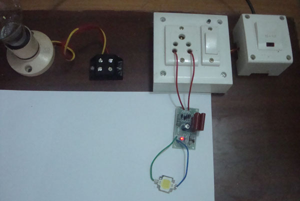
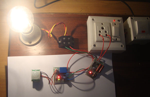
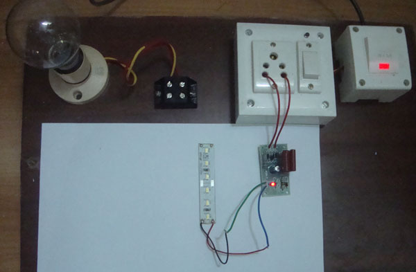
The following images show the working of the high current Transformerless power supply

The Power supply can power many circuits .
It can power a PIR Sensor Circuit with Relay

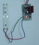
It can power a Strip LED light

It can power an LED Tube Light
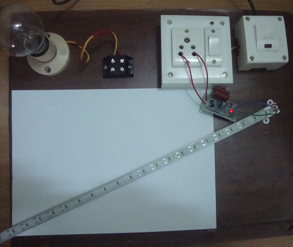

It can power a 10 Watts LED