Presentation
This page describes a method of obtaining low voltage from the 230 V mains, without using a 230 V / 12 V style step-down transformer or transformerless power supplies. This is a method widely used in low consumption electronic circuits. sold commercially, such as some LED night lights, electric coffee makers (for example Senseo) or ultrasonic mole repellants.
Advantages Of The Transformerless Power Supplies
Very economical, minimal power losses, reduced volume, automatic protection against accidental output short circuits, stabilized output voltage.
Disadvantages
Greater risk of electrocution (persistence of 230 V in the supplied assembly, compared to the earth), no longer really suitable when the requested intensity exceeds 50 mA.
Warnings
Must be read before continuing. Any assembly supplied by the mains presents mortal risks, if a minimum of common sense is not respected. The assemblies described in this article do not have isolating transformers, and therefore present a greater danger than the assemblies which have one.
Principle
The basic principle of a transformerless power supply is based on the capacitive reactance of a capacitor . The capacitive reactance is simply the “resistance” that the capacitor opposes to the passage of electric current, and which depends on the one hand on the frequency of the signal passing through it, and on the other hand on the value (capacity) of the capacitor itself. even. In short, we use the capacitor a bit like a resistance, to limit the current and drop a voltage, at a specific frequency.
But the formula R = U / I, which is used to calculate the value of a resistor R according to the voltage drop U that it must cause under a given current I, cannot be used for a capacitor (see page Voltage reduction). For the capacitor, we must use a formula where a term appears related to the frequency of the alternating voltage to be lowered (50 Hz from the 230 V sector, as far as we are concerned). The reactance Xc of a capacitor is expressed in ohms and is equal to:
Xc = 1 / (2 * Pi * F * c)
First way to calculate
This first formula makes it possible to directly express the reactance of the capacitor as a function of its value and the frequency of the signal passing through it:
Xc = 1 / (wc)
where Xc is the reactance in ohms,
w is the pulsation (read omega, equal to 2 * Pi * Freq, Freq in Hertz)
and C is the value of the capacitor in Farad.
The formula can therefore also be written as follows:
Xc = 1 / (2 * Pi * F * c)
where Xc is the reactance in ohms,
Pi = 3.14 (would miss more than that changes),
F is the frequency in Hertz,
and C is the value of the capacitor in Farad.
At a frequency of 50 Hz, which is that of the EDF network, the capacitor allows a current of a few mA to pass per “packet” of 100 nF.
Example N ° 1:
Use of a 470 nF (0.00000047 Farad) capacitor at a frequency of 50 Hz:
Xc = 1 / (2 * 3.14 * 50 * 0.00000047) = 6776 ohms
If input voltage = 230 V and voltage of output = 12 V, then
I = (230 – 12) / 6776 = 32 mA
Example N ° 2:
Use of a 1.7 uF capacitor (0.0000017 Farad) at a frequency of 50 Hz:
Xc = 1 / (2 * 3.14 * 50 * 0.0000017) = 1873 ohms
If input voltage = 230 V and output voltage = 24 V, then
I = (230 – 24) / 1873 = 110 mA
Example N ° 3:
Use of a 1 uF capacitor (0.000001 Farad) at a frequency of 50 Hz:
Xc = 1 / (2 * 3.14 * 50 * 0.000001) = 3184 ohms
If input voltage = 230 V and output voltage = 24 V, then
I = (230 – 24) / 3184 = 65 mA
Example N ° 4:
Use of a 1 uF (0.000001 Farad) capacitor at a frequency of 50 Hz:
Xc = 1 / (2 * 3.14 * 50 * 0.000001) = 3184 ohms
If input voltage = 230 V and voltage of output = 0 V (short-circuit), then
I = (230 – 0) / 3184 = 72 mA
Compared to example N ° 3 (same capacitor value), we see that the current is barely greater and that ‘it does not take on extreme proportions. We have a kind of natural current limitation.
Second way to calculate
Direct calculation of the capacitor value, knowing the desired output voltage U and output current I:
C = I / (2 * 3.14 * 50 * (230 – U))
For the 230 V / 50 Hz network, the formula can be simplified as follows:
C = I / (314 * (230 – U))
where C is the capacitor value in Farad,
I is the maximum desired output current in Amperes
and U is the desired output voltage in Volts
Example N ° 1:
We want U = 12 V and I = 10 mA
C = 0.01 / ( 314 * (230 – 12))
C = 146 nF (we take the standardized value of 150 nF)
Example N ° 2:
We want U = 0 V (short-circuit, what a funny idea) and I = 40 mA
C = 0.04 / (314 * 230)
C = 554 nF (closest normalized value: 560 nF)
Example N ° 3:
We want U = 24 V and I = 110 mA
C = 0.11 / (314 * (230 – 24))
C = 1.7 uF (standardized value 2.2 uF, or paralleling of 1 uF with 680 nF)
We can also return the formula to know the max current according to the value of the capacitor:
I = 2 * 3.14 * F * C * Uc
or in simplified form for the 230 V / 50 Hz network:
I = 314 * C * Uc
where Uc corresponds to the voltage at the terminals of the drop capacitor (230 V – desired output voltage)
Example N ° 4:
We want to know I max for an output voltage U of 12 V, if we use a capacitor of 1 uF
I = 314 * 0.000001 * (230 – 12) = 68 mA
Notes :
– The mains voltage used in the calculations is indeed 230 V which is the effective value, and not 324 V which is the peak voltage, because at the capacitor, we are still working in alternative.
– Due to the rounding applied in the previous formulas, you may find slightly different values depending on the calculation method used. The main thing is all the same to find the correct orders of magnitude (the formula for the second way of calculating, published before 12/09/2009, was wrong – see Corrections and remarks at the end of the page)
Put into practice
The following diagram, which uses a capacitor to lower the current in an LED, should therefore work.
Yes it does. Once, twice, then on the third power on, poof, no more LEDs. And again you will be very lucky if the LED holds the first time. Why ? Because a capacitor that is not in use for a while, discharges. This means that the voltage at its terminals becomes very low or zero after a while.
This also means that it can then be considered as a short circuit. And if we put into service the previous assembly at the same time when the mains wave is at its maximum (more than 310 V peak), the LED sees this voltage at its terminals, which causes a brief and enormous overcurrent, of several amps. .
In general, an LED, even more robust than the average, has difficulty digesting this type of treatment. This assembly is for this reason dangerous, and must not be carried out as it is!But this is only one problem among many. The LED is a polarized component, which only works if a direct voltage is applied to it, and this in the right direction. An alternating voltage is a voltage whose amplitude varies and whose direction (polarity) changes without stopping, and the LED therefore lights up only one alternation in two.
Well, you will say, it’s still 50 Hz and the blinking will therefore be invisible to the human eye because of its retinal persistence. And that’s true. But the LED doesn’t like being with a high reverse voltage (reverse voltage). The reverse voltage supported before breakdown is of the order of a few volts only, and one can suspect that a voltage of some 300 volts slightly exceeds the authorized limit.It is therefore necessary initially to “block” the half-waves not supported by the LED, which is possible thanks to the addition of a simple diode, as shown in the following assembly.
Now the LED no longer receives a reverse voltage that is too high, because during negative half-waves, it is the diode D2 (which we have just added) which conducts. And when it conducts, the voltage at its terminals is less than 1V, which is well below the max reverse voltage tolerated by an LED.
The latter therefore no longer has any reason to grill. Hmm, have you ever forgotten the peak current that can occur when switching on? The following diagram shows that with a simple additional resistor (R1), this potential problem is solved (note at the same time that the value of capacitor C1 has been reduced to 390 nF to drop the current in the LED to approximately 10 mA).
Resistor R1 limits the current draw when the capacitor is discharged. Its value must be determined according to the capacitance of the capacitor and the current peak that is accepted, but in general, it is estimated that its value must be of the order of
R = 3 / I (it is a formula determined empirically)
with R in ohms and I in amperes
Example
If I max = 10 mA (0.01 A), then
R = 3 / 0.01 = 300 ohms
Note: in certain assemblies, a current peak is tolerated much greater than the value of the nominal current, because the peak is brief and the resulting heat dissipation is not always dangerous. For example, an LED with a nominal current of 20 mA, can very well accept an overcurrent of 200 mA if it is occasional, or if the interval between each overcurrent is large compared to the duration of the latter. If we are serious, we document the capacities of the circuit to be supplied, to know its extreme limits.
So here is a montage that is starting to hold up. However, we do not yet have a stabilized output voltage (at the LED), and fluctuations in the mains voltage can cause (small) current variations that we do not want (even if in the example this is not that critical).
If it is possible to use a voltage regulator of the LM78xx type (for example a 12 V regulator such as LM7812), it remains however more economical and less bulky to use a zener diode.. Remember that the maximum output current expected from this type of assembly can hardly exceed a few tens of mA. Here is a new diagram, in which appears a zener diode responsible for limiting the output amplitude to a maximum of 12 V.
Again, the system seems to be working since LED D1 lights up. But if we are curious enough and the idea comes to us of measuring the output voltage to be sure that it does not exceed 12 V, we are entitled to a sacred surprise: the voltage reaches some 2 V, but no more ! Would the choice of a zener diode be in question? What neni. An LED is first and foremost a diode, and when it conducts, the voltage drop does not exceed its nominal voltage, which hardly varies even for a fairly large current variation.
We can therefore liken our LED to a 2 V zener diode. And when we connect two zener diodes of different values in parallel, it is the one of the lowest value which has the last word. In other words, our 12 V zener diode (D3) is absolutely useless in this assembly!It is therefore necessary to rectify the situation, by “isolating” the zener diode from the LED. With resistance, for example.
This time, we have a voltage which reaches 12 V at the terminals of the zener diode D3, and a voltage which hardly exceeds 2 V at the terminals of the LED D1. The resistor R2 wired between these two components therefore causes a voltage drop of 10 V (12 V – 2 V).
With the value of 1 kO given to this resistor R2, we deduce that there is a peak current of 10 mA circulating there, so everything is fine. Of course, if the capacitor C1 had a lower value (for example 100 nF), this current of 10 mA could not be reached. But on the other hand, if the capacitor C1 is of higher value (for example 1 uF), the current in the LED will always be 10 mA because the output voltage, imposed by the zener diode D3, does not vary (or very little ).
We therefore see that the zener, associated with R2,does play a role in regulating output voltage and current. It starts to get interesting, but it is clear that the LED always receives “ends” of alternations, and not a fixed direct voltage. If you have some Basics of linear AC power supplies (not switching power supplies ), you should know that adding a filter capacitor could do us a lot of service. And you’re right, that’s exactly what we need. And presto, a new diagram with a capacitor in parallel on the zener diode!
Well, for example, the LED no longer lights up! And nothing explodes … I don’t feel I was wrong, though. So let’s review what happens with this last diagram, when the halfwaves are positive, that is to say when the voltage on the phase (Ph) is greater than the neutral voltage (N). The mains voltage reaches the zener diode and the capacitor C2, and the latter charges under a voltage which cannot exceed 12 V.
If now the alternation changes direction, i.e. if the voltage on the phase (Ph) is lower than the neutral voltage (N), the diode D2 conducts and … damn it but it is of course! It short-circuits capacitor C2, which therefore discharges immediately. And since the value of capacitor C2 is high, it does nothas no time to fully charge with a single alternation (it needs several). The voltage at its terminals therefore never has time to rise. If we reduce its value to 1 uF, the LED lights up, but we end up again with half-waves, and point of direct voltage.
The solution ? Isolate the zener diode D3 and the filtering capacitor C2 from the sector, when the latter is on its negative half-wave. By adding a diode, like this:when the latter is on its negative alternation. By adding a diode, like this:when the latter is on its negative alternation. By adding a diode, like this:
Diode D4 effectively prevents the capacitor from discharging during negative half-waves. And this time, we have a DC voltage, stabilized and filtered, at the terminals of the zener diode D3. The calculation of C2 answers approximately to the following formula:
C = 200 * (I / U)
where C is expressed in uF
I is the maximum desired output current in mA
and U is the desired output voltage in Volts
General use
The last diagram put into practice shows that we get by with few components, even if as the experiments carried out, we could have the feeling that we would not get out of it, as there was of “problems” to be solved. Finally, we can estimate that the following diagram can be used for other applications than the simple lighting of an LED, which you will admit is still a more interesting exercise than the simple calculation of a falling resistance under a direct voltage … To simplify the task, you will find below a table with some typical values, which can be used as a basis for some experiments. Flashing 006 , for example …
Note: the components in the following diagram have been renumbered compared to the previous diagrams, to take into account the removal of the LED.
12 V / 10 mA output
| Voltage Vout |
Current Iout |
C1 (see note 1) |
R1 (1 W) |
D3 (400 mW) |
C2 (see note 2) |
| 5 V | 20 mA | 820 nF | 150 | 5.1 V | 1000 uF / 16 V |
| 9 V | 10 mA | 390 nF | 300 | 9 V | 220 uF / 16 V |
| 12 V | 40 mA | 1.5 uF | 75 | 12 V | 680 uF / 16 V |
| 15 V | 15 mA | 680 nF | 200 | 15 V | 220 uF / 25 V |
| 24 V | 5 mA | 180 nF | 600 | 24 V | 47 uF / 40 V |
Note 1 : Capacitor C1 should preferably be of class X2 , operating voltage 250 V AC or 400 V DC (or even better 400 V AC or 630 V DC), see paragraph “Choice of series capacitor”. If you need a high value that you can’t find, wire multiple capacitors in parallel to add their value.
Note 2 : Capacitor C2 must always have an operating voltage higher than the desired output voltage
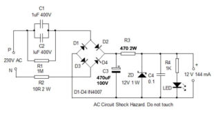
Use of a diode bridge
The use of a diode bridge is quite possible, which is what I did in my 230 V LED lamp .
The efficiency of this circuit is better since the two alternations of the sector are used, which was not the case with the previous assemblies. It is obvious that for an assembly which consumes little, the notion of the output remains quite relative.
The calculation of C1 does not change, it is always it which limits the current available at the output. C2 contributes to the filtering of the voltage rectified by the diode bridge made up of D1 to D4, and the zener diode D5 stabilizes the output voltage at a value close to 12 V (or other voltage value, you choose).
It is possible to do without the zener diode D5 if the supplied circuit (connected between Vout and ground 0 V) does not fear small voltage peaks (current limitation in all cases provided by C1), but in this case be careful : it is advisable toon the one hand to size the operating voltage of capacitor C2 higher and on the other hand to use models for diodes D1 to D4 which are fine. The classic 1N4007 (1000 V / 1 A) are very suitable in all cases. If you have the slightest doubt, leave the D5 zener diode in place.
Addition of a voltage regulator
In some cases, you may need an output voltage that is as well regulated as that obtained with a traditional transformer power supply equipped with an integrated voltage regulator . It is quite possible to mount such a voltage regulator on a mains supply without a transformer, as shown in the following diagram:

This assembly makes it possible to discharge a current of some 40 mA. It should be noted that some mA are already “puffed” by the regulator itself, which consumes even if it is not used. You can of course modify the value of the zener diode and the type of regulator, in order to have an output voltage other than 12 V. For the zener diode, choose a model whose operating voltage is at least 3 higher. V at the output voltage of the regulator, if the latter is a conventional model (voltage drop of at least 3 V for correct regulation). If you opt for a voltage regulator with low voltage drop (LDO), you can then nibble a few additional mA at the output while always maintaining good regulation.
Note : by adopting 2.2 uF capacitors for C1 and C1 ‘, the useful output current can rise to 55 mA, or even 60 mA.
Choice of series capacitor
I previously noted that it was recommended to use a class X2 capacitor for the series capacitor. From a “theoretical” point of view this is not an absolute imperative, but from a “security” point of view it is best. If a capacitor other than class X2 is used, additional protection against overcurrents, at least a fuse, must be provided.
Here’s what to remember:
– the capacity of all the capacitors decreases over time, causing corona effect and corrosion / mold; The corona effect occurs when the voltage applied to the capacitor is close to 300 Vac, and the capacitor is applied a permanent voltage which is close to it (230 Veff sector in our case, from which we basically subtract the operating voltage. lowered final). The corona effect is therefore not the main cause of the degradation of the capacitor, in this application. The main cause is mold and corrosion, which depend on the quality of the mechanical and chemical components used to make the capacitor. An assembly calculated as accurately as possible will work well for a while, then after a while it will presenta malfunction or a total shutdown of its operation (a drop in capacity of 10% may be sufficient to render an assembly non-operational).
– the capacitor used in series must hold up for several years. A good quality capacitor is imperative, forget about the economical Chinese models. Its capacity must not drop too much over the years, since the maximum available current depends precisely on the value of this capacity. Example of a “good” capacitor X2: Kemet series R46.
– the capacitor must withstand overloads, linked to voltage peaks that cannot be avoided on a mains line. The overcurrent which may flow through the capacitor must be limited, to avoid its outright destruction. However, the overcurrent will mainly depend on the impedance of the circuit located after the capacitor. If you don’t know it, consider the worst-case scenario, which is zero impedance. The current limitation will be done by a resistor of a few tens or hundreds of ohms (for example 220 ohms or 1 kO) wired in series with the capacitor.
Note: more than 25 million Senseo coffee makers have been sold worldwide. Their power supply is based on a 470 nF MKP X2 series capacitor, and the vast majority of these coffee makers still work after 5 to 10 years of continuous use (no mains switch, machine permanently powered on with its “small” consumption. of 3 W at rest). Fun to read two different voltage values on the side and top of the capacitor in question … 250 Vac or 275 Vac? Another example, the Faral Tropical 80 inertia radiator, which uses a 680 nF / 275 Vac X2 MKP capacitor:


This heater was in service for 10 years before breaking down. And the failure was not due to the capacitor X2, but to a detached solder on a SMD diode (failure quickly repaired … once located).
Capacitor or falling resistor?
I have seen transformerless mains supplies several times where no capacitor was used as a voltage / current step-down element (in old light shows, in LED temperature displays, among others). Some authors prefer to use power resistors to lower the voltage . This is of course possible, but it is then necessary to know fairly precisely the consumption of the assembly which draws its energy from this type of power supply, and it is of course necessary to choose power resistors capable of continuously withstanding a high voltage drop. The following assembly is an example of what can be done with drop resistors, double output +15 V and +12 V.

Contrary to what one might think, this scheme is not capable of delivering much greater current than its capacitor counterpart. We are indeed quite quickly limited by the power dissipation of resistors R1 to R4, which in the end, and for a similar consumption, take up as much – if not more – space. These resistors, which can heat up quite a bit, must be spaced at least 5 mm to 10 mm from the circuit board to allow air to circulate freely, and the “storage” box must be sufficiently ventilated. The resistors heat up but not the capacitor, it’s up to you.
Link between earth and mass?
In some of the above assemblies, you will have noted the grounding of the neutral wire which comes from the 230 Vac mains socket. It should be noted in this case that the mass and neutral must not be connected to the ground, and even less to a metal case !!! Because imagine for a moment that the two Neutral and Live wires are interchanged … In the best case, you would expose yourself to a trip at the electrical distribution board. And in the most unfortunate case, the user would be quickly “cooled” in the event of direct contact!
Always keep in mind that a transformerless power supply (based on large drop resistance or capacitor) does not have any insulation against the mains!
Specialized integrated circuits
Some manufacturers have developed integrated circuits making it possible to switch “directly” from the voltage of the 110 Vac or 230 Vac network to a low continuous voltage. Some are listed below:
– MAX610 (Maxim) – Output +1.3 Vdc to 15 Vdc – 50 mA
– HIP5600 (Harris) – Output +1.2 Vdc to +50 Vdc – 30 mA max
– HV2405E (Harris ) – +5 Vdc to +24 Vdc output – 50 mA max