

Various automation processes in the industry need control of AC induction motors using AC drives. Presented here is a robust system for switching on/off, varying the speed and direction of rotation of an industrial 3 Phase Induction Motor using VFD and PLC. We use here Delta AC motor drive for its operation.
A simple control panel is wired using an Allen Bradley PLC for demonstration. An extended Intouch wonderware SCADA can be developed also.
An electrical motor is an electromechanical device that converts electrical energy into mechanical energy. In the case of 3-phase AC operation, the most-widely-used motor is the 3 Phase Induction Motor as this type of motor does not require any starting device, being a self-starting motor.
What drives are
Often in the industry, need arises for controlling the speed of a 3 Phase Induction Motor. Delta’s AC motor drives are able to efficiently control motor speed, improve machine automation and save energy. Each drive in its variable frequency drive (VFD) series is designed to meet specific application needs.
AC drives accurately control torque, smoothly handle increased load and provide numerous custom control and configuration operating modes. A VFD can be used to vary speed, direction and other parameters of a 3-phase motor. We use the 2-wire method for controlling the speed and direction of the motor.
Working of a VFD
The first stage of a VFD is the converter, which comprises six diodes, which are similar to check valves used in plumbing systems. These allow current to flow in only one direction; the direction shown by the arrow in the diode symbol. For example, whenever A-phase voltage (voltage is similar to pressure in plumbing systems) is more positive than B- or C-phase voltages, that diode opens and allows current to flow.
When B phase becomes more positive than A phase, B-phase diode opens and A-phase diode closes. The same is true for the three diodes on the negative side of the bus. Thus, we get six current pulses as each diode opens and closes. This is called a 6-pulse VFD, which is the standard configuration for current VFDs.
We can get rid of AC ripple on DC bus by adding a capacitor. A capacitor operates in a similar fashion to a reservoir or accumulator in a plumbing system. It absorbs AC ripple and delivers smooth DC voltage.
The diode bridge converter that converts AC to DC is sometimes just referred to as a converter. The converter that converts DC back to AC is also a converter, but to distinguish it from the diode converter, it is usually referred to as an inverter. It has become common in the industry to refer to any DC-to-AC converter as an inverter.
When we close one of the top switches in the inverter, that phase of the motor is connected to the positive DC bus and voltage on that phase becomes positive. When we close one of the bottom switches in the converter, that phase is connected to the negative DC bus and becomes negative. Thus, we can make any phase on the motor positive or negative at will and can thus generate any frequency that we want. So we can make any phase positive, negative or zero.
Notice that, the output from the VFD is a rectangular waveform. VFDs do not produce a sinusoidal output. This rectangular waveform would not be a good choice for a general-purpose distribution system, but is perfectly adequate for a motor.
 If we want to reduce motor frequency, we simply switch the inverter output transistors more slowly. But if we reduce frequency, we must also reduce voltage in order to maintain V/Hz ratio. Pulse width modulation (PWM) does this.
Imagine, we could control the pressure in a water line by turning the valve on and off at high speed. While this would not be practical for plumbing systems, it works very well for VFDs.
Notice that, during the first half-cycle, voltage is on half the time and off the rest. Thus, the average voltage is half of 480V, that is, 240V. By pulsing the output, we can achieve any average voltage on the output of the VFD.
Selection of Delta VFD-M as AC drive
Delta VFD-M is a sensor-less vector micro AC drive. Its compact design is ideal for small- and medium-horsepower applications. M drive is designed to provide an ultra-low-noise operation and includes several innovative technologies that reduce interference.
This drive can have numerous applications like a packing machine, dumpling machine, treadmill, temperature/humidity-control fan for agriculture and aquaculture, mixer for food processing, grinding machine, drilling machine, small-size hydraulic lathe, elevator, coating equipment, small-size milling machine, robot arm of an injection machine (clamp), wood machine (two-side woodworking planer), edge-bending machine, elasticiser and so on.
Steps for complete motor control
Note: At any point, press Mode to go to the previous step.
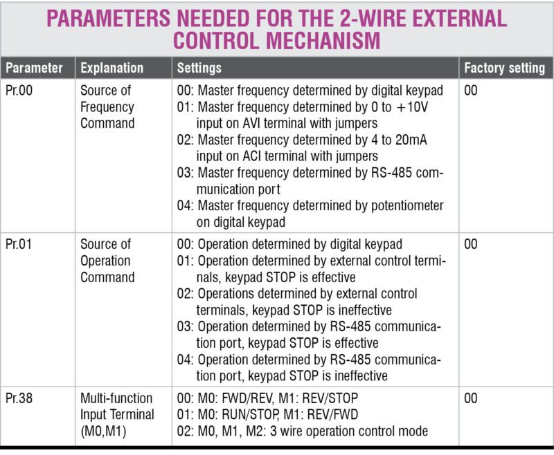
For motor running from external controls, we have three modes of operation; two are 2-wire method and one is 3-wire method. Other than these, there is the default method operable from the digital keypad.
First, carry out a trial run to check all connections.
Test run for VFD
The factory setting of the operation source is from the digital keypad (Pr.01=00). You can perform a trial run by using the digital keypad with the following steps:
VFD-M programming
There are two contacts, M0 and M1. Whenever M0 is closed, VFD goes into run mode. If it is open, there is no rotation of the motor. M1 decides the direction of rotation. If M1 is open, it rotates in forward direction; if closed, in reverse direction.
Parameters for the above mode are set as:
Pr.00 set to 01 (for controlling master frequency via potentiometer)
Pr.01 set to 01 (external controls, via M0, M1)
Pr.38 set to 01 (M0, M1 set as run/stop and fwd/rev)
Set Pr.00 to 00 for controlling master frequency using the digital keypad, and 01 for controlling via potentiometer attached as shown in first pin connection diagram.
Pr.38 should be set to 01 as shown in above diagrams.
Once all these parameters are set, follow 2-wire mode operational steps for running the motor.
Using the PLC
Programmable logic controllers (PLCs) support digital input/output very effectively. So a PLC can also be used to control the operation of a VFD, hence to finally control the connected 3 Phase Induction Motor.
Allen Bradley MicroLogix 1000 PLC is connected to Delta VFD-M and is programmed using Ladder programming using RS Logix.
We connected M0 and M1 to O2 and O3 (outputs) of PLC and control O2 and O3 using Ladder Logic. Fig. 4 shows a logic defined for mode 01, that is, Pr.38 = 01. O:0.0/2 is connected to M0.
When I:0.0/2 is set on, it puts the motor in run mode. Now, even if I:0.0/2 is switched off, O:0.0/2 remains on due to the logic defined. It can only be stopped by pressing I:0.0/2 again.
I:0.0/3 controls O:0.0/5, which, in turn, is connected to M1, which decides the direction of rotation of the motor.
0:0.0/3 is the LED that turns on when the motor is in run mode.
0:0.0/5 is the LED that turns on when the motor is running in forward direction and turns off in reverse rotation.
Love reading this article? You may also like Building a PC Control System Using Wonderware InTouch SCADA and Allen Bradley PLC
Joby Antony is masters in computer technology from the USA, and is currently working as engineer-F at Nuclear Inter-University Accelerator Centre (IUAC), New Delhi. He was also a visiting scientist at CERN, Geneva
Akshay Kumar is a B.Tech student at Delhi Technological University, New Delhi, and currently an intern at IUAC
This article was first published on 22 July 2016 and was recently updated on 27 December 2018.
This content was originally published here.


