

Here is the LM338 Adjustable DC power supply circuit, 1.2V to 30V. It can provide a current maximum to 5A and 10A. If you have used LM317 or LM350.
They are similar, so easy to use with a few components. But LM338 has higher a current than LM317. You can look at a datasheet below more spec.
LM338 Datasheet and Pinout
The LM138/LM238/LM338 are adjustable 3-terminal positive voltage regulators capable of supplying in excess of 5A over a 1.2V to 32V output range.
They are exceptionally easy to use and require only 2 resistors to set the output voltage.
The careful circuit design has resulted in outstanding load and line regulation comparable to many commercial power supplies.
The LM338 or LM138 family is supplied in a standard 3-lead transistor package.
LM338 features
Pinout of LM338K To-03 and LM338T TO-220
Schematic Diagram
Look at the Schematic Diagram inside LM338.
It has a lot of transistors, Zener diodes, resistors, and capacitors. We cannot learn all about it. But I think we can do it.
LM338 Basic circuit Voltage Calculator
Look at a basic circuit. We use only 2 resistors can set the constant output voltage.
Vout = 1.25V x {1+R2/R1} + Iadj x R2
Some said Iadj is very low current(approx 50uA only).
So, we may chop them up. It is shorter and easy to calculate.
Vout = 1.25V x {1+R2/R1}
Which is better?
For example:
You use R1 = 270 ohms and R2= 390 ohms. It causes output is 3.06V
Is it easy? If you have voltages choice with most resistors. In local stores near you.
Look at the Resistors list (without calculating):
You don’t have a calculator, right or too little time or really slow brain. See below, I have an easy solution. For you (me too) choose the right resistor according to the voltage we need.
1.43V : R1 = 470Ω, R2 = 68Ω
1.47V : R1 = 470Ω, R2 = 82Ω
1.47V : R1 = 390Ω, R2 = 68Ω
1.51V : R1 = 330Ω, R2 = 68Ω
1.51V : R1 = 390Ω, R2 = 82Ω
1.52V : R1 = 470Ω, R2 = 100Ω
1.53V : R1 = 390Ω, R2 = 82Ω
1.56V : R1 = 330Ω, R2 = 82Ω
1.57V : R1 = 270Ω, R2 = 68Ω
1.57V : R1 = 470Ω, R2 = 120Ω
1.57V : R1 = 390Ω, R2 = 100Ω
1.59V : R1 = 390Ω, R2 = 100Ω
1.60V : R1 = 240Ω, R2 = 68Ω
1.63V : R1 = 330Ω, R2 = 100Ω
1.63V : R1 = 270Ω, R2 = 82Ω
1.64V : R1 = 390Ω, R2 = 120Ω
1.64V : R1 = 220Ω, R2 = 68Ω
1.65V : R1 = 470Ω, R2 = 150Ω
1.66V : R1 = 390Ω, R2 = 120Ω
1.68V : R1 = 240Ω, R2 = 82Ω
1.71V : R1 = 330Ω, R2 = 120Ω
1.71V : R1 = 270Ω, R2 = 100Ω
1.72V : R1 = 220Ω, R2 = 82Ω
1.72V : R1 = 180Ω, R2 = 68Ω
1.73V : R1 = 470Ω, R2 = 180Ω
1.73V : R1 = 390Ω, R2 = 150Ω
1.76V : R1 = 390Ω, R2 = 150Ω
1.77V : R1 = 240Ω, R2 = 100Ω
1.81V : R1 = 270Ω, R2 = 120Ω
1.82V : R1 = 150Ω, R2 = 68Ω
1.82V : R1 = 330Ω, R2 = 150Ω
1.82V : R1 = 180Ω, R2 = 82Ω
1.83V : R1 = 390Ω, R2 = 180Ω
1.84V : R1 = 470Ω, R2 = 220Ω
1.86V : R1 = 390Ω, R2 = 180Ω
1.88V : R1 = 240Ω, R2 = 120Ω
1.89V : R1 = 470Ω, R2 = 240Ω
1.93V : R1 = 330Ω, R2 = 180Ω
1.93V : R1 = 150Ω, R2 = 82Ω
1.94V : R1 = 270Ω, R2 = 150Ω
1.96V : R1 = 390Ω, R2 = 220Ω
1.97V : R1 = 470Ω, R2 = 270Ω
1.99V : R1 = 390Ω, R2 = 220Ω
2.02V : R1 = 390Ω, R2 = 240Ω
2.03V : R1 = 240Ω, R2 = 150Ω
2.06V : R1 = 390Ω, R2 = 240Ω
2.08V : R1 = 330Ω, R2 = 220Ω
2.10V : R1 = 220Ω, R2 = 150Ω
2.12V : R1 = 390Ω, R2 = 270Ω
2.13V : R1 = 470Ω, R2 = 330Ω
2.16V : R1 = 330Ω, R2 = 240Ω
2.16V : R1 = 390Ω, R2 = 270Ω
2.19V : R1 = 240Ω, R2 = 180Ω
2.23V : R1 = 470Ω, R2 = 390Ω
2.25V : R1 = 150Ω, R2 = 120Ω
2.27V : R1 = 270Ω, R2 = 220Ω
2.27V : R1 = 330Ω, R2 = 270Ω
2.29V : R1 = 470Ω, R2 = 390Ω
2.29V : R1 = 180Ω, R2 = 150Ω
2.31V : R1 = 390Ω, R2 = 330Ω
2.36V : R1 = 270Ω, R2 = 240Ω
2.37V : R1 = 390Ω, R2 = 330Ω
2.40V : R1 = 240Ω, R2 = 220Ω
2.44V : R1 = 390Ω, R2 = 390Ω
2.50V : R1 = 470Ω, R2 = 470Ω
2.57V : R1 = 390Ω, R2 = 390Ω
2.61V : R1 = 220Ω, R2 = 240Ω
2.65V : R1 = 330Ω, R2 = 390Ω
2.66V : R1 = 240Ω, R2 = 270Ω
2.73V : R1 = 330Ω, R2 = 390Ω
2.74V : R1 = 470Ω, R2 = 560Ω
2.75V : R1 = 150Ω, R2 = 180Ω
2.76V : R1 = 390Ω, R2 = 470Ω
2.78V : R1 = 270Ω, R2 = 330Ω
2.78V : R1 = 220Ω, R2 = 270Ω
2.84V : R1 = 390Ω, R2 = 470Ω
2.92V : R1 = 180Ω, R2 = 240Ω
2.96V : R1 = 270Ω, R2 = 390Ω
2.97V : R1 = 240Ω, R2 = 330Ω
3.03V : R1 = 330Ω, R2 = 470Ω
3.05V : R1 = 390Ω, R2 = 560Ω
3.06V : R1 = 270Ω, R2 = 390Ω
3.06V : R1 = 470Ω, R2 = 680Ω
3.08V : R1 = 150Ω, R2 = 220Ω
3.13V : R1 = 220Ω, R2 = 330Ω
3.14V : R1 = 390Ω, R2 = 560Ω
3.18V : R1 = 240Ω, R2 = 390Ω
3.25V : R1 = 150Ω, R2 = 240Ω
3.28V : R1 = 240Ω, R2 = 390Ω
3.35V : R1 = 220Ω, R2 = 390Ω
3.37V : R1 = 330Ω, R2 = 560Ω
3.43V : R1 = 270Ω, R2 = 470Ω
3.43V : R1 = 390Ω, R2 = 680Ω
3.43V : R1 = 470Ω, R2 = 820Ω
3.47V : R1 = 220Ω, R2 = 390Ω
3.50V : R1 = 150Ω, R2 = 270Ω
3.54V : R1 = 180Ω, R2 = 330Ω
3.55V : R1 = 390Ω, R2 = 680Ω
3.70V : R1 = 240Ω, R2 = 470Ω
3.82V : R1 = 180Ω, R2 = 390Ω
3.83V : R1 = 330Ω, R2 = 680Ω
3.84V : R1 = 270Ω, R2 = 560Ω
3.88V : R1 = 390Ω, R2 = 820Ω
3.91V : R1 = 470Ω, R2 = 1K
3.92V : R1 = 220Ω, R2 = 470Ω
3.96V : R1 = 180Ω, R2 = 390Ω
4.00V : R1 = 150Ω, R2 = 330Ω
4.02V : R1 = 390Ω, R2 = 820Ω
4.17V : R1 = 240Ω, R2 = 560Ω
4.33V : R1 = 150Ω, R2 = 390Ω
4.36V : R1 = 330Ω, R2 = 820Ω
4.40V : R1 = 270Ω, R2 = 680Ω
4.43V : R1 = 220Ω, R2 = 560Ω
4.44V : R1 = 470Ω, R2 = 1.2K
4.46V : R1 = 390Ω, R2 = 1K
4.50V : R1 = 150Ω, R2 = 390Ω
4.51V : R1 = 180Ω, R2 = 470Ω
4.63V : R1 = 390Ω, R2 = 1K
4.79V : R1 = 240Ω, R2 = 680
5.04V : R1 = 330Ω, R2 = 1K
5.05V : R1 = 270Ω, R2 = 820Ω
5.10V : R1 = 390Ω, R2 = 1.2K
5.11V : R1 = 220Ω, R2 = 680Ω
5.14V : R1 = 180Ω, R2 = 560Ω
5.17V : R1 = 150Ω, R2 = 470Ω
5.24V : R1 = 470Ω, R2 = 1.5K
5.30V : R1 = 390Ω, R2 = 1.2K
5.52V : R1 = 240Ω, R2 = 820Ω
5.80V : R1 = 330Ω, R2 = 1.2K
5.88V : R1 = 270Ω, R2 = 1K
5.91V : R1 = 220Ω, R2 = 820Ω
5.92V : R1 = 150Ω, R2 = 560Ω
5.97V : R1 = 180Ω, R2 = 680Ω
6.04V : R1 = 470Ω, R2 = 1.8K
6.06V : R1 = 390Ω, R2 = 1.5K
6.32V : R1 = 390Ω, R2 = 1.5K
6.46V : R1 = 240Ω, R2 = 1K
6.81V : R1 = 270Ω, R2 = 1.2K
6.92V : R1 = 150Ω, R2 = 680Ω
6.93V : R1 = 330Ω, R2 = 1.5K
6.94V : R1 = 180Ω, R2 = 820Ω
7.02V : R1 = 390Ω, R2 = 1.8K
7.10V : R1 = 470Ω, R2 = 2.2K
7.33V : R1 = 390Ω, R2 = 1.8K
7.50V : R1 = 240Ω, R2 = 1.2K
8.07V : R1 = 330Ω, R2 = 1.8K
8.08V : R1 = 150Ω, R2 = 820Ω
8.19V : R1 = 270Ω, R2 = 1.5K
8.30V : R1 = 390Ω, R2 = 2.2K
8.43V : R1 = 470Ω, R2 = 2.7K
8.68V : R1 = 390Ω, R2 = 2.2K
9.06V : R1 = 240Ω, R2 = 1.5K
9.58V : R1 = 330Ω, R2 = 2.2K
9.77V : R1 = 220Ω, R2 = 1.5K
9.90V : R1 = 390Ω, R2 = 2.7K
10.03V : R1 = 470Ω, R2 = 3.3K
10.37V : R1 = 390Ω, R2 = 2.7K
10.63V : R1 = 240Ω, R2 = 1.8K
11.25V : R1 = 150Ω, R2 = 1.2K
11.44V : R1 = 270Ω, R2 = 2.2K
11.48V : R1 = 330Ω, R2 = 2.7K
11.67V : R1 = 180Ω, R2 = 1.5K
11.83V : R1 = 390Ω, R2 = 3.3K
12.40V : R1 = 390Ω, R2 = 3.3K
12.71V : R1 = 240Ω, R2 = 2.2K
13.75V : R1 = 330Ω, R2 = 3.3K
15.31V : R1 = 240Ω, R2 = 2.7K
16.25V : R1 = 150Ω, R2 = 1.8K
16.53V : R1 = 270Ω, R2 = 3.3K
16.59V : R1 = 220Ω, R2 = 2.7K
18.44V : R1 = 240Ω, R2 = 3.3K
19.58V : R1 = 150Ω, R2 = 2.2K
20.00V : R1 = 220Ω, R2 = 3.3K
23.75V : R1 = 150Ω, R2 = 2.7K
24.17V : R1 = 180Ω, R2 = 3.3K
28.75V : R1 = 150Ω, R2 = 3.3K
For example, you need 20V 5A power supply. You look at 20.00V : R1 = 220Ω, R2 = 3.3K.
Protection Diodes
You do not want to see this IC damage, right? As it is expensive. Read now to keep it is healthy.
In the circuit diagram above. We use the external capacitors with any IC regulator. Sometimes, we need to add the protection diodes to prevent low current parts in the regulator.
When these capacitors(like 20uF) discharge. It will have low enough internal series resistance to deliver 20A spikes when shorted.
Although this surge is short. But it has enough energy to
damage parts of the IC.
Look at n the circuit diagram.
We connect the output capacitor(C1) to the regulator. Then,
the input shorts. Next, the output capacitor will discharge into the output of the regulator.
We use D1, D2 1N4002 to absorbs this current spike to protects the regulator circuits.
The discharge current depends on 3 factors.
In the LM138. this discharge path is through a large junction. It can tolerate a 25A surge with no problem.
This is not true of other types of positive regulators.
Note: For output capacitors of 100 uF or less at the output of 15V or less, there is no need to use diodes.
The bypass capacitor(C2) on the adjustment terminal can dis-
charge through a low current junction.
The Discharge occurs when either the input or output is shorted. Internal to the LM138 is a 50X resistor. which limits the peak discharge current.
No protection is needed for output voltages of 25V or less and 10 mF capacitance.
So, In-the circuit shows an LM138 with protection diodes included for use with outputs greater than 25V and high values of output capacitance.
It is easy, right?
1.25V to 30V, 5A Variable power supply using LM338
We may have many ways such as: to modify the LM317 Variable Regulator 0-30V 1A. By adding the power transistor MJ2955 in a circuit. As following Adjustable Voltage and current regulator IC power supply .
Or You may build the Variable dc regulator 0-30V 5A circuit, as well. But these methods. Rather cumbersome and wasting too much money.
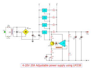
However, we can build this circuit easily and cheaply, By using the packages IC No. LM338 only one, Similar to the LM317 IC number, but it can supply up to 5A, like the circuit shown in Fig.
How this circuit works
The transformer T1 converts the AC 220V to 24 Vac, so be rectified the current by the bridge diode rectifier BD1 – 10A 400V. Until DCV has come out that the filter capacitor C1 is equal to 35 volts.
The IC1 is the heart of the operation of this circuit. By the voltage output value obtained from the IC depends on the voltage value at the Adj pin of IC1, or can be varied by adjusting the VR1.
However, the output voltage will be approximately equal to 1.25+1.25VR1/R1
The output voltage at the output pin of the IC1 is a more powerful filter with the capacitor C3.
Parts you will need
IC1: LM338K, LM338P
D1: Bridge Diode 10A
D2, D3: 1N4007, 1000V 1A diode
R1: 220Ω 0.5W resistors 5%
R2: 12K 0.5W Resistors 5%
VR1: 10K Potentiometer
C1,C3: 4700uF 50V Electrolytic
C2: 0.1uF 50V
LED 5mm
T1: Transformer, 24V 5A secondary
The Building
You must solder all devices in the PCB to completely, for the IC LM338K should install with a large heat sink. and all device has the poles. Caution connected the correct, especially electrolytic capacitor.
Figure 2 The PCB layout and components layout
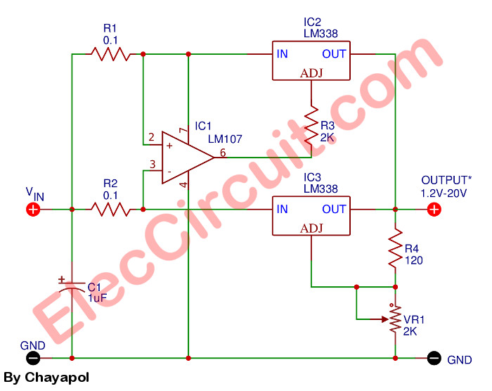
1-20V, 10A Adjustable DC Power Supply
1.2V-20V 10A adjustable dc power supply using LM338
If you want Variable Regulated Power Supply high current more than 10A up. I would recommend this circuit. Because build easy, use LM338 and LM107 again.
The normal LM338 has the current about 5A. Then, must use 2 pcs. It causes more current up to 10A.
The VR1 adjusts an output voltage of 1.2V to 20V to cover usual usability. This idea can protect all errors with two LM338.
See other LM338 circuits
I want you to get the most out. The LM338 is very usable. Because we can use it in many circuits as follows. Of course, we would like to focus on simple circuits as the main.
0 to 22V Adjustable voltage regulator
How to start the output voltage at “zero”. In normal it will begin at 1.2V.
But we can use other negative voltage to offset this voltage to the zero.
We use the LM113 Zener regulator IC, 1.2V.
This is a simple constant current regulator. It will limit the output current by adjusting R1.
Iout = Vref / R1
5A current Regulator circuit
The current will get a constant current of 5A. We use only one resistor to control the output current.
The output current = Vref / R1.
R1 = 0.24 ohms at 2 watts.
We need to use the right power of Resistor, too.
Adjustable Current Regulator circuit
If you want to adjust the output current. We adjust R2 to set the current from 0A to 5A.
This circuit uses LM117 to set the current at Adj of LM338.
Check out these related articles, too:
If you want to see examples of projects. Using LM338 to multiple connections in parallel. To boost the higher current.
Up to $20 shipping discount on first order now: https://jlcpcb.com/quote
GET UPDATE VIA EMAIL
I always try to make Electronics Learning Easy.
This content was originally published here.


