

Shannon Fano Elias encoding algorithm is a precursor to arithmetic coding in which probabilities are used to…
Imagine a distributed cloud spread all over your campus. The main server is sitting somewhere on the…
Audio frequencies range from 20Hz to 20kHz but these frequencies are not heard in the same way….
This project turns on and turns off a laser LED after every second. It can also monitor its own supply voltage level. The circuit can be extended for use as an audio-visual alarm system for security applications.
Keyes KY-008 laser transmitter module is available at www.ebay.com. But there is a lot of confusion regarding this particular module; it is impossible to find its datasheet or any kind of related document from the Internet.
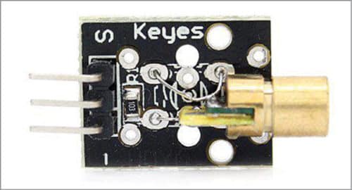
KY-008 laser LED module has three pins, as shown in Fig. 1. The pins are labelled (from left to right) as: pin 1 as S, pin 2 (centre) with no label and pin 3 with – (minus sign). Pin 2 outputs the exact same voltage as the supply voltage, which is connected at pin 1. Pin 2 can be used in the following ways:
1. To monitor incoming power supply or voltage level.
2. To use as triggering input to alarm circuit when voltage at pin 2 drops (such as when someone cuts the power supply of laser LED, or when voltage drops below an acceptable level for an application). In short, this module provides an option to monitor its own power supply.
When you connect a 5V power supply to the laser module, a red-dot laser beam appears.
Circuit and working of interfacing of KY-008 laser LED module with Arduino
Circuit diagram for interfacing of KY-008 laser LED module with Arduino is shown in Fig. 2.
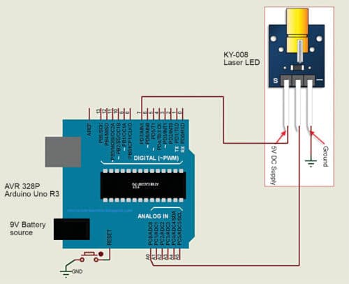
Connect pins 7 and Gnd of Arduino to pins 1 and 3 of KY-008 module, respectively. Run the first sketch (onoff.ino) to turn the laser on and off every second. Next, connect pin A0 (ADC channel 0) of Arduino to pin 2 of the laser module. The second sketch (laser_status.ino) outputs the voltage status on pin 2 of the module to Arduino’s serial monitor. The author’s prototype is shown in Fig. 3.

Software
Circuit operation is done using the software loaded into the internal memory of Arduino Uno R3. The program is written in Arduino programming language. Arduino IDE 1.6.4 is used to compile and upload the program/sketch. ATmega328P on Arduino Uno comes with a pre-programmed bootloader that allows you to upload a new code to it without using an external hardware programmer. Connect Arduino to the PC and select the correct COM port in Arduino IDE.
The first sketch (onoff.ino) turns the laser on and off without sending any information to the serial monitor. The second sketch (laser_status.ino) turns the laser on and off, and at the same time reads the voltage coming from centre pin 2 of the module, which is displayed on the serial monitor of Arduino. You can experiment with this sketch as follows:
1. Play with the delay in the code for turning the laser on or off, faster or slower.
2. Place a resistor in series with the power supply line and then check voltages on the serial monitor.
3. Connect a piezo buzzer to pin 2. Every time the laser turns on, the piezo buzzer will sound an alarm.
Pamarthi Kanakaraja is an assistant professor in Usha Rama College of Engineering and Technology, Andhra Pradesh
This content was originally published here.


