

 During summers, most people are too lazy to water the potted plants on their rooftop gardens every day. Explained in this section is a simple and exciting automatic plant watering system that you can build yourself in just a few hours. It is an Arduino based automatic plant watering system that uses a soil moisture sensor. The author’s prototype is shown in Fig. 1.
Automatic plant watering system circuit and working
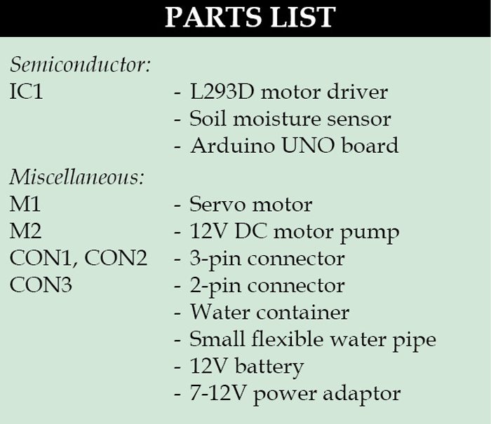
The circuit diagram of the automatic plant watering system is shown in Fig. 2. The circuit comprises an Arduino UNO board, a soil moisture sensor, a servo motor, a 12V water pump and an L293D (IC1) motor driver IC to run the water pump.
You can power the Arduino board using a 7V to 12V wall wart or plug-in adaptor or solar panel. You need a separate 12V battery or power supply or solar panel for the pump motor.
 Soil moisture sensor
Two types of soil moisture sensors are available in the market—contact and non-contact sensors. A contact soil sensor (as shown in Fig. 3) is used in this project because it has to check soil moisture to measure the electrical conductivity.
The moisture sensor provides an analogue output, which can easily be interfaced with Arduino. In this project, two sensors can be connected to analogue pins, A0 and A1, of the Arduino board. Each sensor has four pins (Vcc, Gnd, Ao and Do) available for interfacing with the Arduino board. Here, digital output pin (Do) is not used. The water pump and servo motor are controlled by Arduino connected to digital pins 3 and 9, respectively. That is, the servo motor signal control pin is connected to pin 9 of the Arduino board.
 The program in the Arduino reads the moisture value from the sensor every 20 seconds. If the value reaches the threshold value, the program does the following three things:
Software program
The program is written in Arduino programming language. The code is well commented and is easy to understand. Compile the autowatering.ino code and upload it to the microcontroller, using Arduino IDE version 1.
The sensor will calibrate by itself once it is kept in the soil and the threshold value will be shown on the serial monitor in Arduino. Serial debugging is available in this program. Comment out if you do not wish to use the serial monitor.
Construction and testing
An actual-size, single-sided PCB layout of the automatic plant watering system is shown in Fig. 5 and its component layout in Fig. 6.
Assemble the components on the PCB to minimise errors. Alternatively, you can assemble them on a breadboard or Arduino prototyping shield or a general-purpose PCB. Upload the code to Arduino UNO board and install the sensors in the soil of the potted plants. Do not immerse the sensors fully inside the soil.
Install the pump in a water container (refer Fig. 7) that can hold a few litres of water. attach the water pipe on the servo motor horn as shown in Fig. 8.
Download PCB and Component Layout PDF: Click Here
Download Source Code: Click Here
Before powering the circuit on, you need to keep in mind the following macro definitions in the code:
Place the flower pots where the pipe from the servo motor horn can easily reach them. When the moisture level dips below 600, servo horn rotates at an angle of 70 degrees. That is, after servo motor horn moves 70 degrees toward the first pot, the motor pump will be on for five seconds and then stop automatically. Then, the servo returns to its original position. Similarly, if you are using a second sensor, the servo motor horn will move to 145 degrees to the second biggest pot, motor pump will be on for eight seconds and then stop automatically. The servo returns to its original position.
Further application
Using the Arduino UNO board, you can water six different potted plants. By adding a few more lines in the code, you can water even more plants—by using the Arduino Mega 2560 board which has more analogue input pins.
You can also add an Ethernet or Wi-Fi shield and use the Twitter library, which will tweet from your plants side to send messages like: I need water, the tank is empty, refill the tank, thanks for the water, and so on.
A 16×2 LCD can be added to indicate moisture levels.
You can also enable the circuit to refill the tank after a few days, depending on the volume of the tank.
The author is a student of applied electronics and instrumentation engineering at JRE School of Engineering, Greater Noida. He likes making projects with Arduino.
This article was first published on 5 October 2016 and was recently updated on 24 December 2018.
This content was originally published here.


