Regular computer power supply transforms the input 110V or 220V AC into different DC output voltages ideal for running the PC’s motherboard along with other computer hardware connected to it and that can be identified in the ATX power supply pinout diagram. 
Power supplies are cited as working with a specific power output specified in Watts. The greater elements (CD/DVD drives, hard drives, fans.. ) you will have within your computer, the higher the power needed out of your power supply. It is possible to identify the power necessary for your pc utilizing a power supply calculator.
Computer power supply units or PSU provide the energy to the PC hardware through a variety of wires with connectors. The common criteria for different PSU form factors created for usage with personal computer systems are characterized in Intel’s layout guides that can be regularly modified.
Computer ATX power supply Pinout diagram
At first a motherboard had been powered by just a single 20 pin connector. Recent models of ATX power connectors is actually a 24 pin connector made up of one 20 pins block that is joined to a 4 pins block as a way to respect backward compatibility with old 20 pin connectors motherboards.
| ATX power connector version 2.0 | ATX Pinout version 1.0 |
 |
 |
ATX standards consists of not just PSU, but additionally interface to motherboard and case. Along with the older AT standard, ATX 2.0 offers one more +3.3V voltage line, a connector chain-lined with the 20pin plus a Power-ON line which enables computer software to shut off the Power Supply Unit. The ATX connector pin-out standard demands the PSU to provide 3 principal outputs:
- +3. 3 V with tolerance of ±0. 165 V
- +12V with tolerance of ±0. 60 V
- +5 V with tolerance of ±0. 25 V
A small electric power -12V with tolerance of ±1. 2 V and a 5VSB standby voltage ±0. 25 V are likewise necessary. A voltage of -5V was initially needed as it has been delivered to the ISA bus, yet it became useless upon the elimination of the ISA bus within today’s Computer systems and was eliminated on later editions of the ATX standard.
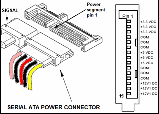
SATA Power Connector Pinout
A SATA 15 pin power supply connector is among the standard power connectors of peripherals in modern PC systems. That ATX power connector is now a conventional ATX connector for any SATA structured optical devices and HDDs.
It’s wafer-based, 15-pin design. The relatively big amount of pins are utilized to deliver 3 distinct voltages 3.3 VDC, 5 VDC, and 12 VDC. Every single voltage is presented by 3 pins ganged together plus 5 pins to GND. That is due to the fact tiny pins are not able to offer enough current for certain equipment. A single pin out of each one of the 3 voltages is additionally employed for hotplugging. The identical physical connections are utilized in 2.5 and 3.5 inches laptop hard drives.
|
Following is the conventional 15 pin SATA power connector pinout as of Edition 2.2 in the ATX Standards.
Pay attention: There furthermore exists a couple of not frequent SERIAL ATA power supply connectors: a 9 pin connector that provides +3. 3V and +5V known as micro connector and also a 6 pin connector that provides +5V known as slimline connector. The connector pinout tables for these connectors change from the one presented here. Pay attention: In case you are employing that pinout table to check your ATX power supply voltages, remember that the voltages need to be in ATX given tolerances. |
|
Computer power supply tips:
In the mother board power connector, the pin number 12 may be Brown (not Blue) in some power supply connectors, pin 8 might be White (not Gray) and pin 18 can also be Blue (not White), Furthermore, certain ATX power supply pinout do not respect wires color coding.
When power supply switch is turned on then pin 14 goes from 0V to 3. 7V and the standby Pin 9 goes from 0V to 5V.
The Pin called PS_ON within the connector pin-out is active by pushing and releasing the start key when the power supply is at standby.
Shorting the connector pin 14 (/PS_ON) to GND (COM) causes power supply to switch ON and PWR_OK to change to +5V, this is very helpful for PSU troubleshooting.


it’s interested