

 This project presents a user-friendly way of controlling four electrical equipment using an LCD-based interactive menu. Usually, each equipment is controlled by a pushbutton switch. In this design, instead of four pushbuttons, only two pushbuttons are used to control the operations of four electrical equipment. Pushbuttons provide a hardware interrupt to Arduino, which executes the corresponding interrupt sub-routine to implement the control algorithm. The authors’ prototype is shown in Fig. 1.
Circuit and working
The circuit diagram of the electrical equipment control system using Arduino is shown in Fig. 2. Hardware includes Arduino Uno board, 16×2 LCD, four-channel relay board, two pushbutton switches and a few other components.
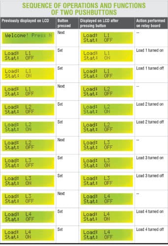
In this project, two momentary pushbuttons (S1 and S2), namely, Next and Set, are provided so that you can select which load to control. Load number and status of each load are also displayed on the LCD menu. On pressing Next, you can choose between various loads to control. On pressing Set, you can turn on or off a particular load.
When a particular pushbutton is pressed, its circuit generates an interrupt, which is detected by Arduino. And it executes an interrupt service routine. RC networks used in conjunction with the two pushbuttons are used for debouncing the pressed switch. Functions of the two pushbuttons are shown in the sequence of images in the table (next page).
Major components used in this project are described below.
Arduino Uno
Arduino Uno is an AVR ATmega328P microcontroller (MCU)-based development board with six analogue input pins and 14 digital I/O pins. The MCU has 32kB ISP flash, 2kB RAM and 1kB EEPROM. It can operate at a clock frequency of 16MHz.
In this project, digital I/O pins 1, 8, 9 and 10 of Arduino are configured as output pins and are used to control the relays. Digital I/O pins 2 and 3 are configured as interrupt pins. Digital I/O pins 4, 5, 6, 7, 11 and 12 are used to interface the LCD with Arduino.
 SPDT relay
A relay is an electromechanical switch. A four-channel relay board used in this project is shown in Fig. 3. Relays used here are of single-pole double-throw (SPDT) type. In this type of relay, output side has three terminals, namely, normally open (NO), normally closed (NC) and common (C).
When the relay is not energised, NC and C terminals are short-circuited, and NO and C terminals are open-circuited. When relay coil is energised, NC and C terminals are open-circuited, and NO and C terminals are short-circuited.
Arduino program uses the LCD in 4-bit mode. LCD data lines D4 to D7 are configured for reading data from Arduino. Pins 1 and 2 of the LCD are connected to Gnd and 5V, respectively, of Arduino. Read/write pin (pin 5) of the LCD is connected to Gnd. A 10kW preset is provided for adjusting the contrast of the display.
Source code lcd_interactive.ino written in Arduino uses LiquidCrystal.h header file provided by Arduino library for working with the LCD.
lcd.begin(16, 2) function helps configure the 16×2 character LCD.
attachInterrupt(0,nbpress,rising) function calls interrupt handler nbpress whenever a signal connected to Interrupt 0 pin (pin 2) of Arduino makes a low-to-high, that is, rising-edge transition.
attachInterrupt(1,sbpress,rising) function calls interrupt handler sbpress whenever a signal connected to Interrupt 1 pin (pin 3) of Arduino makes a low-to-high, that is, rising-edge transition.
Construction and testing
Connect the circuit as shown in the circuit diagram. Compile and upload the program to Arduino from Arduino IDE. To power Arduino, use either a normal USB cable from USB port of the computer or an external 5V DC power supply source. Alternatively, use a 9V battery at Vin pin of Arduino to power it.
Connect the relay board at connector CON1 to connect the four inputs (IN1 through IN4) of the relay board to Arduino to control four electrical loads (L1 through L4). Note that, relay board used here requires a separate 12V DC power supply.
Download source folder
Saikat Patra is passionate about electronics and MCU-based embedded system applications.
Shibendu Mahata is M.Tech (gold medallist) in instrumentation and electronics engineering from Jadavpur University. Currently, he is pursuing PhD from NIT Durgapur. He is interested in MCU-based, real-time embedded signal processing and process control systems.
This content was originally published here.


