

This robot with a camera is placed in a remote location to capture the environment in visual form using Raspberry Pi (RPi). The captured visuals are displayed on the user’s virtual reality (VR) headset.
An added feature allows the camera to move in the direction of the user’s head movements. This gives the user a real-time experience as if he is present where the robot is located.
The robot can also be moved in any direction through an app installed in the user’s smartphone.
Virtual reality
The video captured by RPi camera can be viewed on a smartphone placed in the virtual reality (VR) headset. The project lets the user experience virtual reality through VR headset. Dual-screen mode is enabled in the smartphone for this purpose.
The smartphone reads the accelerometer and magnetometer data of the direction in which the user turns his head, say, right or left. This data is sent to the modem over Wi-Fi and to the RPi board, which, in turn, provides these values as inputs to the servo motors.
Two servo motors are used to move the camera—one for the vertical movement and the other for the horizontal movement. So when you turn your head along with VR headset to the right side, the RPi camera will also turn to the right direction.
Circuit and working
The block diagram of virtual telepresence robot is shown in Fig. 1. RPi is the brain of the system. It receives input from the smartphone via Wi-Fi, and then sends controlling pulse to the servo motors to move the RPi camera.
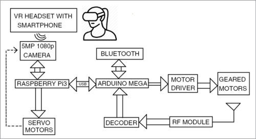
The smartphone also provides input to the Arduino Mega (Board2) for the purpose of navigation or movement of the robot. The motor driver IC and geared motors are connected at the end of the navigation circuit.
The commands to run the robot can be sent via Bluetooth or RF module from the smartphone. In this example, Bluetooth is used.
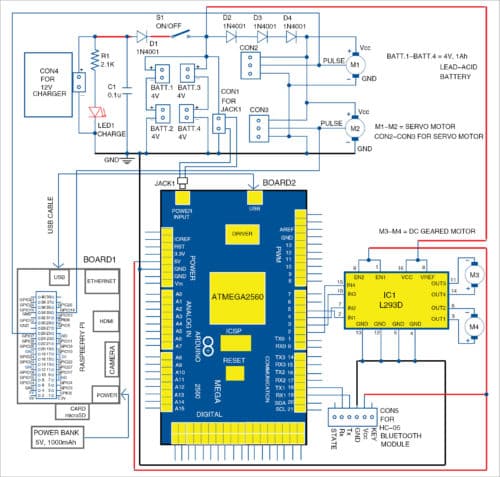
The main circuit diagram of virtual telepresence robot is shown in Fig. 2. The project has following sections: 12V charger, 8V power supply, Raspberry Pi board, Arduino Mega 2560 board, servo motors, DC geared motors and Bluetooth module. Along with these you also require an Android smartphone with relevant app, Python and PHP codes for Raspberry Pi, and Arduino sketch for Arduino board.
Power supply
The first stage of the circuit is a 12V charger for charging rechargeable batteries. Four lead-acid rechargeable batteries, each of 4V, 1Ah, are arranged in series and parallel combination to provide 8V power supply. If the batteries are connected in series, the final voltage gets added up and current remains the same. If the batteries are connected in parallel, current adds up and voltage remains the same. Thus, you get 8V, 2Ah power supply by connecting two each in series and then the two sets in parallel.
Diode D1 is used to block discharging of the battery through LED1 and capacitor C1. The diode also makes the circuit stable and controls temperature while charging.
The 8V power supply is used to power the Arduino, motor driver IC and other modules. When switch S1 is open, the battery supply to servos is cut off. Three series diodes (D2 through D4) reduce the voltage to around 6V for safe operation of servo motors.
A 5V power bank is used to power the Raspberry Pi.
Navigation
The navigation circuit controls movement of the robot. It consists of Arduino Mega 2560 board (Board2), HC-05 Bluetooth module, L293D motor driver (IC1), and two DC geared motors M3 and M4.
Directional data or command from the smartphone is sent to the navigation circuit through HC-05 Bluetooth module. It is processed by the Arduino and then fed to the motor driver IC, which drives the geared motor in the required direction. Commands are given to the Bluetooth Electronics app installed in the smartphone.
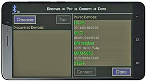
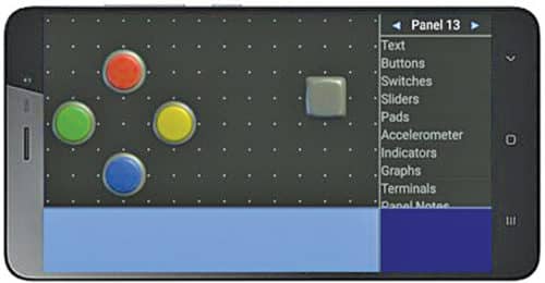
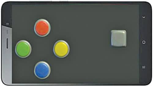
First, you need to open the Bluetooth Electronics app and pair with the HC-05 module as shown in Fig. 3. Once the two devices are paired, the buttons are edited in the app and configured with English alphabet characters. Each direction (forward, backward, right and left) is assigned a character. Four buttons are used as shown in Fig. 4. When these buttons are pressed, the corresponding characters get transmitted.
HC-05 Bluetooth module receives the characters and sends these to the Arduino pins (transmitter and receiver). The Arduino processes this data and compares with the Arduino program. The corresponding digital values are sent to input pins of L293D IC. The driver IC provides more current in order to make the motor move in the required direction.
Depending on the data received from the Bluetooth module, the motor moves in forward or backward direction.
Virtual Telepresence Robot Using Raspberry Pi
Shamin P. Shaji (left) is SoC design verification engineer at Wafer Space Semiconductors Technologies Pvt Ltd. — P. Careena is assistant professor at Amal Jyothi College of Engineering, Kanjirapally. Steffy Don, Rahul Shaji and Sharon Mariam George are electronics hobbyists
This content was originally published here.


