Discover the Feedback Circuits
According to Dictionary.com the word “Feedback” referring to electronics, is the process of returning part of the output of a circuit, system, or device to the input, either to oppose the input (negative feedback) or to aid the input (positive feedback).
Do you know that there are actually quite a number of feedback circuits in electronic equipment without you realizing it? The most common feedback circuit in electronic equipment is the Switch Mode Power Supplies. The feedback circuit in SMPS is used either for regulation, protection or for both function purposes. If without/lost of the feedback signals, certain circuits like the CPU/MCU will not function properly and the power supplies may go into shutdown mode. If you want higher chances in successfully repair electronic equipment, you need to understand the function of the feedback circuit. I will share with you some of the typical feedback circuits that can be found in Monitor.
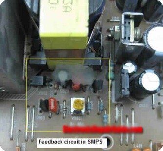
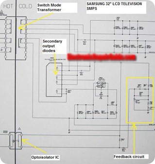
a) The Switch Mode Power Supply (SMPS) feedback circuit mostly can be found in the area at the secondary side of the Optoisolator IC. This feedback signal is tapped from the B+ voltage line and is needed to regulate the power supply through the Optoisolator IC so that the output power will always be steady (see photo below).
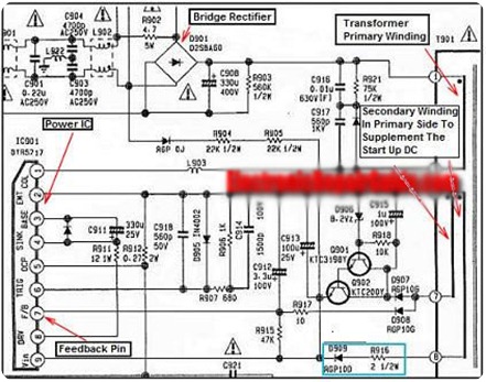
In some design, the feedback signal is taken from one of the winding in primary side instead from the output B+ line as seen in photo below. Please observe the power IC (I901) pin 7 written as FB which means “Feedback”.
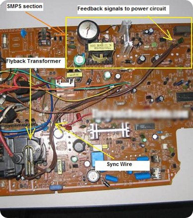
b) If you are repairing CRT Monitor and Television, I’m sure you have seen the “Sync wire” before which is located on the flyback transformer. The signal from the wire is send back (feedback) from the flyback transformer to the switch mode power supply in order to synchronize the frequency. If you remove this wire from the circuit, you will see that the display have wavy lines running vertically across the display. That means, in the future, if you see any wavy lines across the screen, your logical thinking will tell you to check the sync wire and the corresponding components.
c) There are few ways to control the output of the high voltage in the anode. One of the ways is to tap a feedback signal from one of the flyback transformer pins. The signal generated from the flyback transformer will be fedback to the Pulse Width Modulation IC (PWM) UC3842 thus controlling the total amount of high voltage at the anode. If the Monitor have shutdown problem due to higher than normal high voltage (exceeding 24 KVDC), I guess you need to check all the corresponding components along the feedback line.
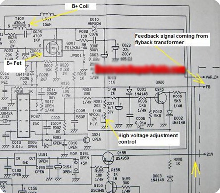
d) I have seen a unique Monitor design that used the feedback from one of the flyback transformer pins that sent to the CPU in order for the Monitor to function properly. That means, although the CPU is working fine, if the flyback transformer have problem and no signal feedback to the CPU within a second or two, the power LED will change from Green to Amber color. If you do not understand this type of circuit, you may have thought that either the CPU or EEprom IC (data corrupted) have problem. Troubleshooting the wrong circuit will definitely waste your precious time.
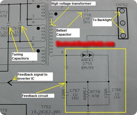
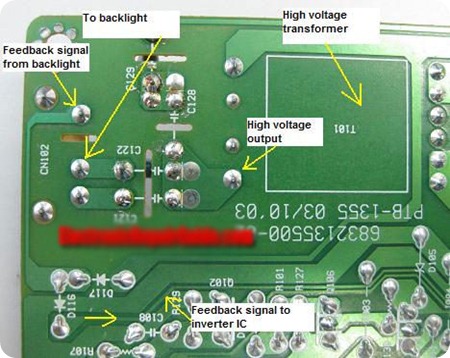
e) Ever wonder why when the LCD Monitor/LCD Television/Notebook backlight have problem (broken or weak backlight) the display will shutdown? Thanks to the feedback circuit that was designed to send the error signal back to the inverter IC, thus shutting down the waveform to the high voltage transformer. If the high voltage transformer did not energize, there will be no high voltage produced thus the backlight will not light up.
Conclusion- The above article is not necessary applicable only to Monitor electronic repairers, you may use it as a guide to understand your type of electronic equipment (i.e. – Television (CRT/LCD), Satellite Receiver, DVD, Audio Equipment, Xbox and etc). Fully aware of the feedback circuit that present in your type of equipment will add advantage to you because it could help you to solve a particular problem fast that was caused by the feedback circuit. What you need to do now is to get the schematic diagrams of your type of electronic equipment and begin to pinpoint/search how many feedback circuits do the equipment have and jot down all the feedback circuits and analyze it. This will greatly improve the repair rate of your type of equipment.


